
*This post is sponsored by The Home Depot
Links below are affiliate links, clicking on them helps me keep this site going at no extra cost to you . Thank you for supporting my site.

The corner blocks provide rigidity to the chair rails and a platform for the chair insert to sit atop.
Corner blocks on chairs serve two purposes. The corner blocks offer rigidity to the chair rails and prevent the rails from racking. They also provide a platform for the a seat insert to sit on. Since I’m using an upholstered plywood seat insert, I decided to place the top of my corner blocks 3/4” below the top surface of the chair rails.
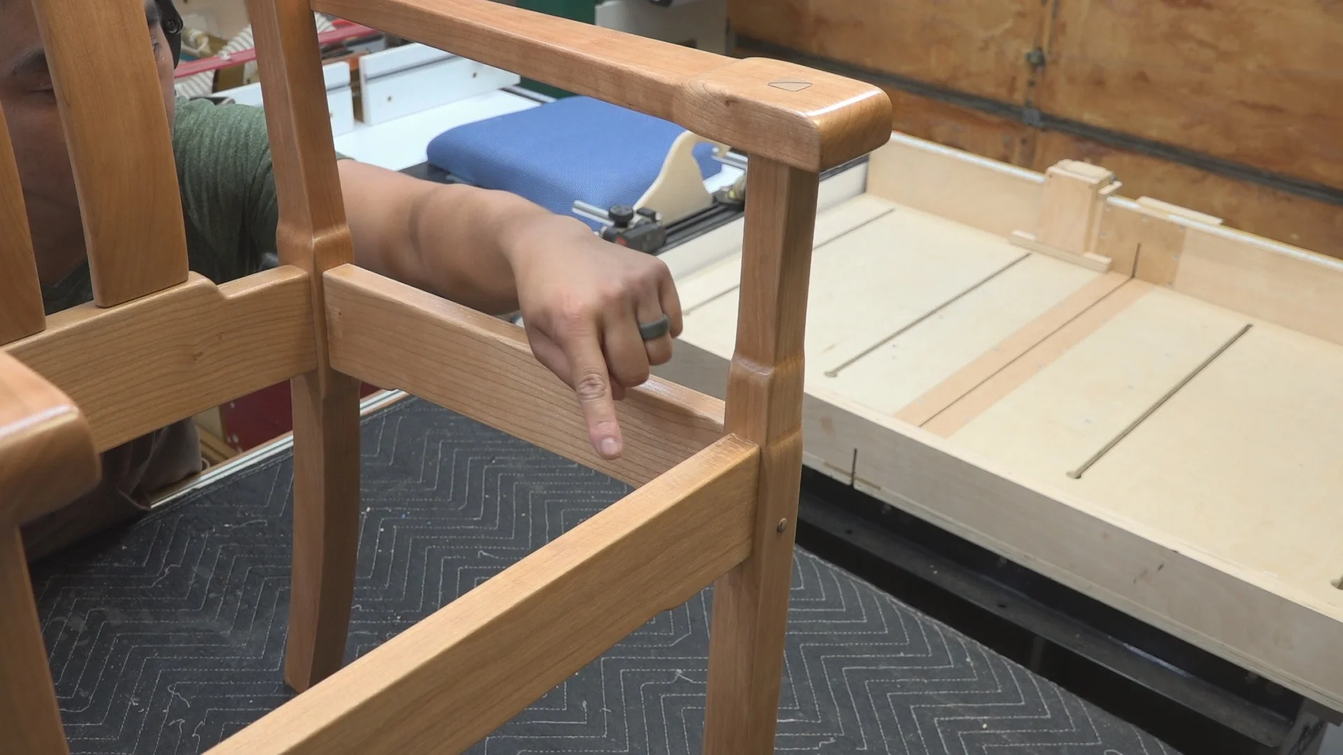
The corner blocks are placed diagonally between chair rails.

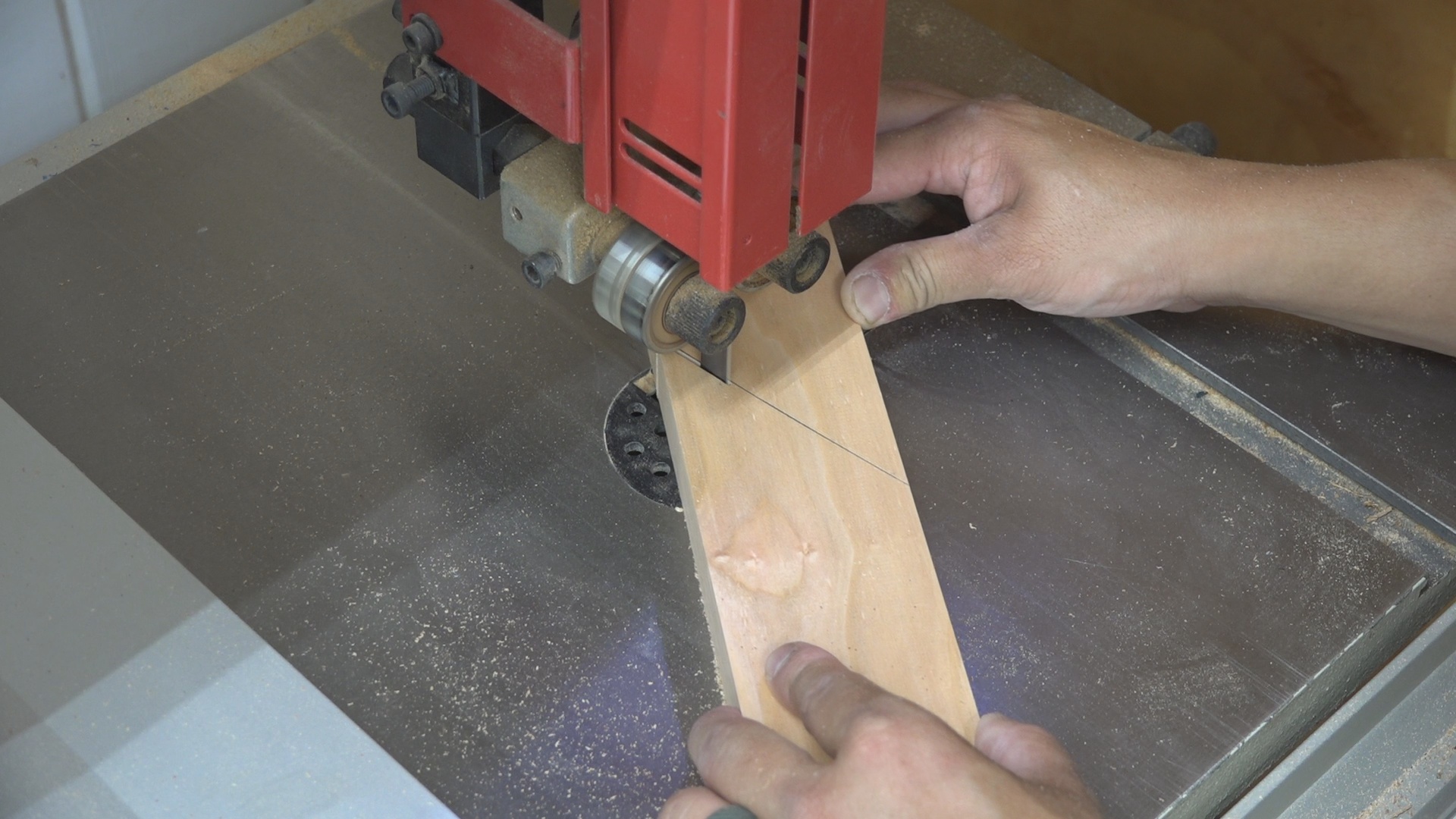
Ripping Cherry to rough width.
I first rip 5/4 Cherry stock to rough width on the bandsaw. In this case, I made the cut at 2-5/8” wide. This is the safest way to rip rough sawn lumber. I then go to the jointer to flatten material and create a 90 degree edge. I then run the material through the planer to a final thickness of 1” and final width of 2-1/2”.

I first flatten the face.

I then joint the edge perpendicular to the flattened face.

Planing to final thickness (1”) and final width (2-1/2”)
The front corner blocks are cut at 45 degrees and 53 degrees. I first cut the 45 degree miter and then the 53 degree miter on the miter saw. The length of these blocks is not that important but I made sure that the corner blocks were long enough to ensure they would clear the front chair legs.

I first cut the 45 degree miter on the miter saw.

I then cut the 53 degree miter on the miter saw.
The counter bored 3/8” holes in the corner blocks were drilled on the drill press using a Forstner bit. I used a shop made drill press fence on my drill press table, a stop block, and a hand screw clamp to offer lateral support to the work piece.

The drill press fence, stop block, and hand screw clamp helps support the work piece while drilling an angled surface.
To make sure each corner block is attached at the proper height, I used a jig and spring clamp to reference the proper height. This jig is nothing more than two pieces of the 1/2” plywood attached at a right angle.

A jig and spring clamp set to the proper height to attach the corner blocks.
I screwed the corner blocks into place using a 1-1/2” washer head screw (Kreg brand screw). I used the Ridgid OCTANE 18V Hammer Drill/Driver and 6-Mode Impact Driver to predrill and drive the screws. The hammer drill/driver produces a whopping 1,300 in.-lbs. of torque which is way more than I need for this operation. The impact drive produces 2,400 in.-lbs. of torque which is also way more than I need to drive a 1-1/2” screw. What I really liked about the impact driver are the 6 different modes available for increased versatility (3 Speeds and 3 Specialty Modes). This ensures that the impact drive is providing the proper amount of torque so that you don’t over drive or under drive a screw. I used the Auto Stop mode which prevents the screw from being over tightened. It worked perfectly.

I pre-drilled and drove the screw in for the corner blocks Using the Ridgid Octane 18V Hammer Drill/Driver and 6-Mode Impact Driver.
The back corner blocks were cut at 53 degrees but also had to be cut to accommodate the curve of the back rail. I traced the inside curve of the back rail on the corner block and then cut the curve on the bandsaw. I then sanded the curve to the drawn line on the disc sander.
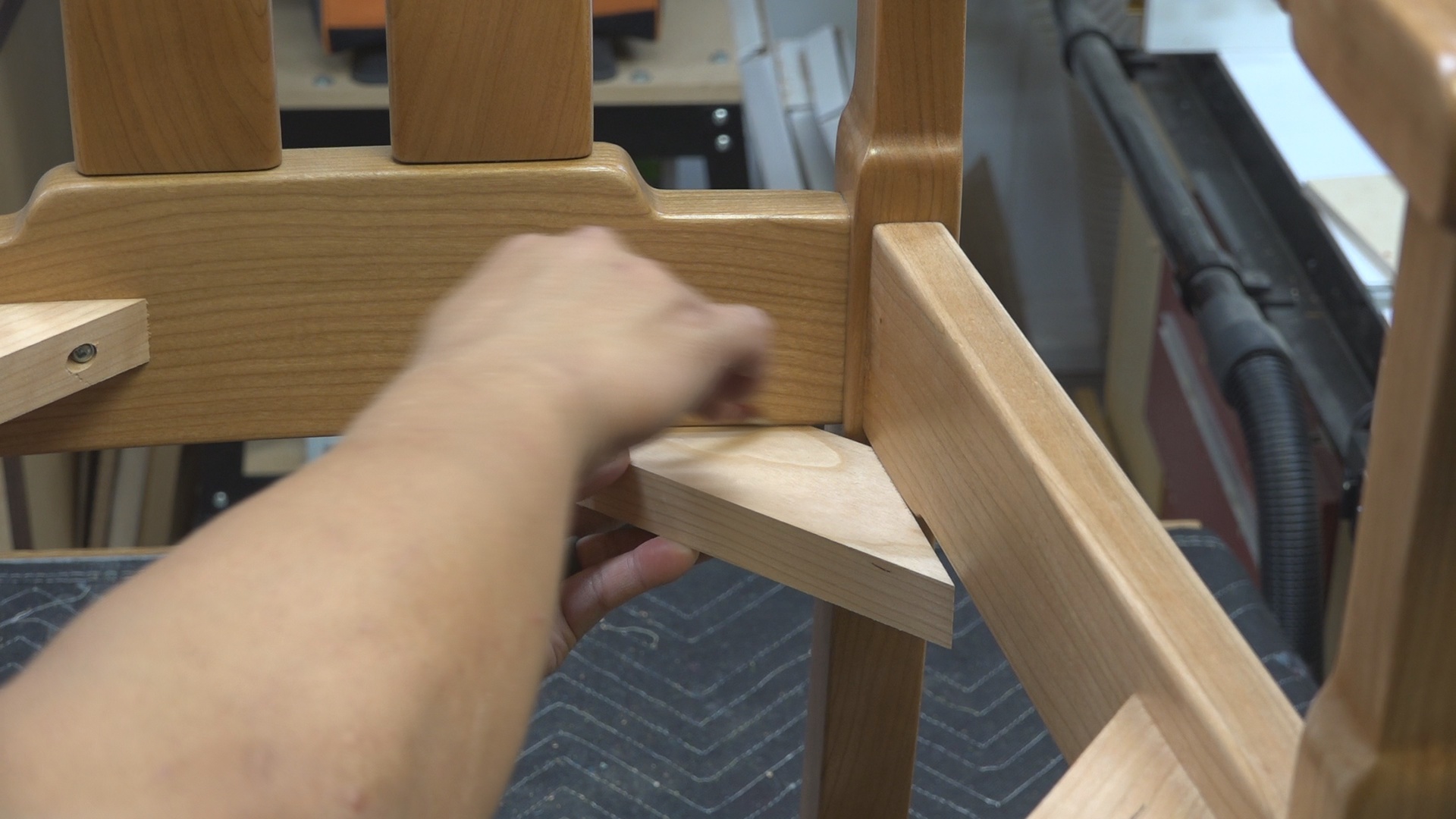
I traced the curve of the back rail.
I cut the traced line on the bandsaw.

I used the disc sander clean up the bandsaw marks to get a perfect fit.
Lastly, I attached the back corner blocks in the same way as before by using the clamping jig and the Ridgid Octane Hammer Drill/Driver and Impact Driver.

Attaching the back corner blocks. The jig and spring clamp establish the height. I used the Ridgid Octane Hammer Drill/Driver and Impact Driver to set the screws to attach the corner blocks.

I used the prototype chair insert to test the fit of the corner blocks. I was very happy with the results.